If you model behavior using a Mealy or Moore machine, and follow the steps for implementing it, you get synchronous sequential circuits.
We're going to implement a synchronous counter. We contrast this synchronous counter with a asynchronous counter (a counter where all flip flops were not hooked to the same clock. This was discussed in another set of notes.
This is an unusual counter. Normally, if you have a standard up-counter, it counts up starting from (0)k (zero, repeated k times), all the up way to (1)k (one, repeated k times), and then starts back at (0)k and counts up again. (We could implement a down counter than counts backwards, too).
However, there's no reason we can't implement a counter that counts 00, 01, 10, and then back to 00. There might be no reason why we should do so, either.
Nevertheless, since we can implement an up-counter of this kind let's do so. It's a good exercise.
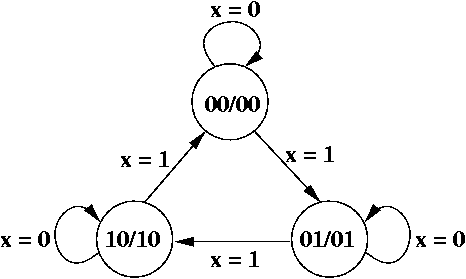
Here's the 3-state up counter, as a Moore machine.
| Row | q1 | q0 | x |
| 0 | 0 | 0 | 0 |
| 1 | 0 | 0 | 1 |
| 2 | 0 | 1 | 0 |
| 3 | 0 | 1 | 1 |
| 4 | 1 | 0 | 0 |
| 5 | 1 | 0 | 1 |
| 6 | 1 | 1 | 0 |
| 7 | 1 | 1 | 1 |
For counters, it's almost always the case that the state label and the outputs are identical.
| Row | q1 | q0 | x | q1+ | q0+ | z1 | z0 |
| 0 | 0 | 0 | 0 | 0 | 0 | ||
| 1 | 0 | 0 | 1 | 0 | 0 | ||
| 2 | 0 | 1 | 0 | 0 | 1 | ||
| 3 | 0 | 1 | 1 | 0 | 1 | ||
| 4 | 1 | 0 | 0 | 1 | 0 | ||
| 5 | 1 | 0 | 1 | 1 | 0 | ||
| 6 | 1 | 1 | 0 | d | d | ||
| 7 | 1 | 1 | 1 | d | d |
They aren't completely identical because there is no state 11. We always place d (don't cares) in the rows of states that don't exist.
| Row | q1 | q0 | x | q1+ | q0+ | z1 | z0 |
| 0 | 0 | 0 | 0 | 0 | 0 | 0 | 0 |
| 1 | 0 | 0 | 1 | 0 | 1 | 0 | 0 |
| 2 | 0 | 1 | 0 | 0 | 1 | 0 | 1 |
| 3 | 0 | 1 | 1 | 1 | 0 | 0 | 1 |
| 4 | 1 | 0 | 0 | 1 | 0 | 1 | 0 |
| 5 | 1 | 0 | 1 | 0 | 0 | 1 | 0 |
| 6 | 1 | 1 | 0 | d | d | d | d |
| 7 | 1 | 1 | 1 | d | d | d | d |
| Row | q1 | q0 | x | q1+ | q0+ | z1 | z0 | D1 | D0 |
| 0 | 0 | 0 | 0 | 0 | 0 | 0 | 0 | 0 | 0 |
| 1 | 0 | 0 | 1 | 0 | 1 | 0 | 0 | 0 | 1 |
| 2 | 0 | 1 | 0 | 0 | 1 | 0 | 1 | 0 | 1 |
| 3 | 0 | 1 | 1 | 1 | 0 | 0 | 1 | 1 | 0 |
| 4 | 1 | 0 | 0 | 1 | 0 | 1 | 0 | 1 | 0 |
| 5 | 1 | 0 | 1 | 0 | 0 | 1 | 0 | 0 | 0 |
| 6 | 1 | 1 | 0 | d | d | d | d | d | d |
| 7 | 1 | 1 | 1 | d | d | d | d | d | d |
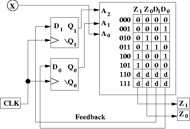
This basically consists of drawing the ROM correctly. The main mistakes that you're like to make is: copying columns incorrectly, adding more columns than the outputs and the flip flops control, failing to label the address bits and the addresses.
It's a good idea, when you draw the circuit to compare your version to the one here, and ask "What did I leave out?"
What the above exercise should illustrate is that once you can model something using a Moore or Mealy machine, it's straight-forward to implement afterwards. There is a mechanical process, which you practice, and it becomes easy after doing it a few times.