We're going to look at two ways to make a parallel-load register. A parallel-load register has two basic operations, which are summarized by the following table.
| c | Operation |
| 0 | Hold |
| 1 | Parallel Load (z31-0 = x31-0) |
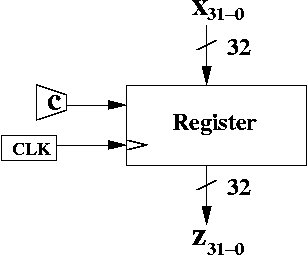
Here's a black box diagram for a parallel load register.
A 32 bit register has 32 bits of data input, x31-0. It also has 32 bits of output, which is labelled, z31-0.
There's also a clock input. The register can only be updated at positive clock edges. If c = 0 (at the positive clock edge), then the output of the register is unchanged. If c = 1 (at the positive clock edge), x31-0, is loaded in parallel, and those 32 bits are output as z31-0.
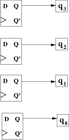
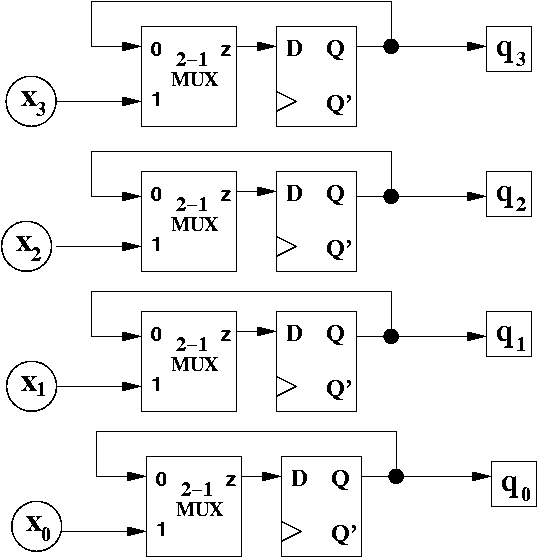
Since we need to store 4 bits, we'll need 4 flip flops. Here's the initial diagram.
At this point, we need to figure out how to make a choice between two options: we either want to hold, or we want to parallel load.
What combinational logic device can we use that allows us to pick between one of many different inputs (or in this case, between one of two inputs)? We should use a 2-1 MUX!
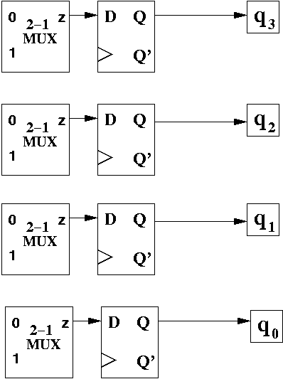
For the "0" input, we want to hold the value. What does that mean? Each flip flop is currently outputting a bit. We want to maintain that same value.
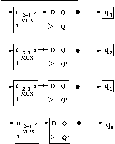
How can we do that with a D flip flop? Recall that a D flip flop reads in the value of D, and makes that the output, Q. If we want to have the output stay the same, we need to feed back the output back into the input, through input 0 of the MUX.
When c = 1 we want to parallel load the input. We accomplish this by feeding in the input x3-0 into the "1" input of the 2-1 MUX.
The circuit isn't quite complete. We should add the clock and the control input, as well.
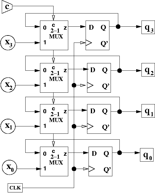
The control input is drawn in a "cheating" way. I draw the line going in at the top MUX, and being drawn "straight through" to the other MUXes. You can choose to draw it this way, if you want, or draw it less ambiguously.
The first question is how to "hold" using T flip flops. For D flip flops, we did that by feeding the output of the D flip flop back into the input (through the MUX).
We don't want to feed the output back, because that's not how T flip flops work (try to figure out happens if you do feed it back). Recall the two operations of a T flip flop: hold and toggle. You already have a way to "hold" the value. Input the value 0 into the T input!
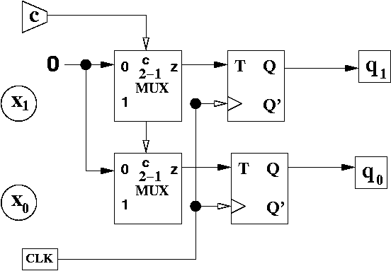
The hard part is to make a T flip flop parallel load. It's quite easy to do it for D flip flop, since all you do is feed in the input directly to D.
So what does it mean to parallel load? It means to get a flip flop to output the value of x. So, let's think about what that means. Suppose the flip flop current outputs 1, and we want to parallel load 0. This means, we need to toggle the output, so that it changes the output from 1 to 0.
Let's come up with a table to list out all the possibilities.
| What we want to load (x) | What is currently being output (q) | What we need to do (T) |
| x = 0 | q = 0 | HOLD (T = 0) |
| x = 0 | q = 1 | TOGGLE (T = 1) |
| x = 1 | q = 0 | TOGGLE (T = 1) |
| x = 1 | q = 1 | HOLD (T = 0) |
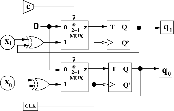
We can derive a Boolean expression for T. If you look carefully, it's just the XOR of x and q.
T = x XOR q
Here's the circuit:
| c1c0 | Operation |
| 00 | Hold |
| 01 | Parallel Load (z31-0 = x31-0) |
| 10 | Logical Shift Left 1 bit |
| 11 | Logical Shift Right 1 bit |
This requires a 4-1 MUX.
A parallel load register either holds the value of the outputs, or parallel loads the inputs to make them outputs. They can be designed with D or T flip flops, although it's easier to use D flip flops.