
Never fear though. Even though it may be difficult to learn how to implement Mealy and Moore machines, most people will tell you that it's a very mechanical process. That is, once you learn it, it's like following a cookbook recipe.
Of course, you might ask why you should learn how to implement Mealy and Moore machines, but we'll defer that to the next set of notes.
and eventually create a black box circuit that looks like:
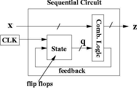
Recall that a sequential circuit stores state information. If we have k states, that state information requires ceil( lg( k ) ) flip flops. Since each flip flop stores one bit, then the state stores ceil( lg( k ) ) bits of information.
In fact, that information is the state label. For example, in the FSM diagram above, there's two bits used in the state, thus you have q1q0 = 00 to mean that some state label is 00.
This is basically a truth table that records the information of the finite state machine.
This is usually simple, because you have to encode each state of the finite state machine using ceil( lg( k ) ) bits. Or even better, someone's already given you an FSM with that information encoded.
Choosing the kind of flip flop you want is usually an academic exercise. You'll often be told to use a certain flip flop, so you need to be able to handle the kind give.
We'll talk about the excitation table momentarily.
Look at the diagram of the black box in the previous section. See the box inside the black box labelled combinational logic? We're using a ROM (read-only memory) to implement the combinational logic.
Technically, a ROM is not combinational logic. It's memory, thus, it basically has flip flops in it. However, you could use gates to implement the equivalent behavior of a ROM, using sum-of-products representation.
It's like someone told you to fold a piece of paper this way, then that way, and eventually when you're done, they say congratulations, you've made a "glurble". You're happy and proud of this paper concoction you've created! "A glurble!", you exclaim.
Then you realize you have absolutely no idea what you've made. You know the steps, but you don't know why it matters.
For now, the quickest way to learn this is to follow the steps, understand how they work, and then try to get the big picture a little later.
We'll implement the Moore machine shown above. The Moore machine has two bits for the state and one bit for the input.
| Row | q1 | q0 | x |
| 0 | 0 | 0 | 0 |
| 1 | 0 | 0 | 1 |
| 2 | 0 | 1 | 0 |
| 3 | 0 | 1 | 1 |
| 4 | 1 | 0 | 0 |
| 5 | 1 | 0 | 1 |
| 6 | 1 | 1 | 0 |
| 7 | 1 | 1 | 1 |
Since the input and state variables are the truth table inputs, we list out all possibilities. There are 1 input variable plus 2 state variables = 3 truth table inputs, thus 23 rows in the truth table.
It means we're current in state q1q0 = 00 and we see an input of x = 0 (at a positive edge).
The reason for doing it in this order (as opposed to putting input variable, then state variables) is to handle every possible input per state, before moving onto the next state.
For example, look at the Moore maching above. In state 00, if we see an input of a 0, then we go to state 10. In state 00, if we see an input of a 1, then we go to state 01. Let's put that information in the "truth table output" section (shown in green).
| Row | q1 | q0 | x | q1+ | q0+ |
| 0 | 0 | 0 | 0 | 1 | 0 |
| 1 | 0 | 0 | 1 | 0 | 1 |
| 2 | 0 | 1 | 0 | ||
| 3 | 0 | 1 | 1 | ||
| 4 | 1 | 0 | 0 | ||
| 5 | 1 | 0 | 1 | ||
| 6 | 1 | 1 | 0 | ||
| 7 | 1 | 1 | 1 |
Now let's go to state 01. In state 01, if the input is 0, you stay in state 01. If it's 1, you go to state 10.
| Row | q1 | q0 | x | q1+ | q0+ |
| 0 | 0 | 0 | 0 | 1 | 0 |
| 1 | 0 | 0 | 1 | 0 | 1 |
| 2 | 0 | 1 | 0 | 0 | 1 |
| 3 | 0 | 1 | 1 | 1 | 0 |
| 4 | 1 | 0 | 0 | ||
| 5 | 1 | 0 | 1 | ||
| 6 | 1 | 1 | 0 | ||
| 7 | 1 | 1 | 1 |
Now we go to state 10. In state 10, if we see a 0, we head to state 01. If we see a 1, we go to state 00. We fill that in.
| Row | q1 | q0 | x | q1+ | q0+ |
| 0 | 0 | 0 | 0 | 1 | 0 |
| 1 | 0 | 0 | 1 | 0 | 1 |
| 2 | 0 | 1 | 0 | 0 | 1 |
| 3 | 0 | 1 | 1 | 1 | 0 |
| 4 | 1 | 0 | 0 | 0 | 1 |
| 5 | 1 | 0 | 1 | 0 | 0 |
| 6 | 1 | 1 | 0 | ||
| 7 | 1 | 1 | 1 |
Finally, there is no state 11. So, in that case, we don't care what happens if we are in that state. We can fill whatever we want. However, to emphasize that we don't care, we fill in the next state with d's, which indicate "don't care".
| Row | q1 | q0 | x | q1+ | q0+ |
| 0 | 0 | 0 | 0 | 1 | 0 |
| 1 | 0 | 0 | 1 | 0 | 1 |
| 2 | 0 | 1 | 0 | 0 | 1 |
| 3 | 0 | 1 | 1 | 1 | 0 |
| 4 | 1 | 0 | 0 | 0 | 1 |
| 5 | 1 | 0 | 1 | 0 | 0 |
| 6 | 1 | 1 | 0 | d | d |
| 7 | 1 | 1 | 1 | d | d |
All we need to now is fill out the outputs.
Since this is a Moore machine, here are the rules for filling out the outputs. For each state, look at the output. Thus, state 00 has output z1z0 = 01.
State 00 is in row 0 and row 1, where q1q0 = 00.
| Row | q1 | q0 | x | q1+ | q0+ | z1 | z0 |
| 0 | 0 | 0 | 0 | 1 | 0 | 0 | 1 |
| 1 | 0 | 0 | 1 | 0 | 1 | 0 | 1 |
| 2 | 0 | 1 | 0 | 0 | 1 | ||
| 3 | 0 | 1 | 1 | 1 | 0 | ||
| 4 | 1 | 0 | 0 | 0 | 1 | ||
| 5 | 1 | 0 | 1 | 0 | 0 | ||
| 6 | 1 | 1 | 0 | d | d | ||
| 7 | 1 | 1 | 1 | d | d |
State 01 has output 11. State 01 is in rows 2 and 3.
State 10 has output 11. State 01 is in rows 4 and 5.
State 11 doesn't exist, so we put "d" in rows 6 and 7 for the output columsn (in blue).
| Row | q1 | q0 | x | q1+ | q0+ | z1 | z0 |
| 0 | 0 | 0 | 0 | 1 | 0 | 0 | 1 |
| 1 | 0 | 0 | 1 | 0 | 1 | 0 | 1 |
| 2 | 0 | 1 | 0 | 0 | 1 | 1 | 1 |
| 3 | 0 | 1 | 1 | 1 | 0 | 1 | 1 |
| 4 | 1 | 0 | 0 | 0 | 1 | 1 | 1 |
| 5 | 1 | 0 | 1 | 0 | 0 | 1 | 1 |
| 6 | 1 | 1 | 0 | d | d | d | d |
| 7 | 1 | 1 | 1 | d | d | d | d |
However, in a test situation, you'll be told which flip flops to use.
We need a flip flop for each bit used in a state. There are two bits, q1q0, so two flip flops are needed.
Let's implement q1 with a D flip flop, and q0 with a T flip flop. We'll label them D1 (to match up with q1) and T0 (to match up with q0).
We add two more columns to the table, D1 and T0.
| Row | q1 | q0 | x | q1+ | q0+ | z1 | z0 | D1 | T0 |
| 0 | 0 | 0 | 0 | 1 | 0 | 0 | 1 | ||
| 1 | 0 | 0 | 1 | 0 | 1 | 0 | 1 | ||
| 2 | 0 | 1 | 0 | 0 | 1 | 1 | 1 | ||
| 3 | 0 | 1 | 1 | 1 | 0 | 1 | 1 | ||
| 4 | 1 | 0 | 0 | 0 | 1 | 1 | 1 | ||
| 5 | 1 | 0 | 1 | 0 | 0 | 1 | 1 | ||
| 6 | 1 | 1 | 0 | d | d | d | d | ||
| 7 | 1 | 1 | 1 | d | d | d | d |
We now look at column q1 and q1+. They've been highlighted.
These columns refer to flip flop D1. Basically, look at each row. For example, in row 0, you see q1 = 0 and q1+ = 1. Thus, you need to make D = 1 (based on the excitation table).
In row 1, you see q1 = 0 and q1+ = 0. Thus, you need to make D = 0 (based on the excitation table).
But recall that the D excitation table basically said D = Q+. So, all we have to do is to copy the q1+ columns over to D1.
| Row | q1 | q0 | x | q1+ | q0+ | z1 | z0 | D1 | T0 |
| 0 | 0 | 0 | 0 | 1 | 0 | 0 | 1 | 1 | |
| 1 | 0 | 0 | 1 | 0 | 1 | 0 | 1 | 0 | |
| 2 | 0 | 1 | 0 | 0 | 1 | 1 | 1 | 0 | |
| 3 | 0 | 1 | 1 | 1 | 0 | 1 | 1 | 1 | |
| 4 | 1 | 0 | 0 | 0 | 1 | 1 | 1 | 0 | |
| 5 | 1 | 0 | 1 | 0 | 0 | 1 | 1 | 0 | |
| 6 | 1 | 1 | 0 | d | d | d | d | d | |
| 7 | 1 | 1 | 1 | d | d | d | d | d |
Now we focus on columns q0 and q0+.
| Row | q1 | q0 | x | q1+ | q0+ | z1 | z0 | D1 | T0 |
| 0 | 0 | 0 | 0 | 1 | 0 | 0 | 1 | 1 | |
| 1 | 0 | 0 | 1 | 0 | 1 | 0 | 1 | 0 | |
| 2 | 0 | 1 | 0 | 0 | 1 | 1 | 1 | 0 | |
| 3 | 0 | 1 | 1 | 1 | 0 | 1 | 1 | 1 | |
| 4 | 1 | 0 | 0 | 0 | 1 | 1 | 1 | 0 | |
| 5 | 1 | 0 | 1 | 0 | 0 | 1 | 1 | 0 | |
| 6 | 1 | 1 | 0 | d | d | d | d | d | |
| 7 | 1 | 1 | 1 | d | d | d | d | d |
Now look at row 0. We have q0 = 0 and q0+ = 0. The T flip flop excitation says that T must hold (i.e., T = 0) for that to happen.
Now look at row 1. We have q0 = 0 and q0+ = 1. The T flip flop excitation says that T must toggle (i.e., T = 1) for that to happen.
| Row | q1 | q0 | x | q1+ | q0+ | z1 | z0 | D1 | T0 |
| 0 | 0 | 0 | 0 | 1 | 0 | 0 | 1 | 1 | 0 |
| 1 | 0 | 0 | 1 | 0 | 1 | 0 | 1 | 0 | 1 |
| 2 | 0 | 1 | 0 | 0 | 1 | 1 | 1 | 0 | |
| 3 | 0 | 1 | 1 | 1 | 0 | 1 | 1 | 1 | |
| 4 | 1 | 0 | 0 | 0 | 1 | 1 | 1 | 0 | |
| 5 | 1 | 0 | 1 | 0 | 0 | 1 | 1 | 0 | |
| 6 | 1 | 1 | 0 | d | d | d | d | d | |
| 7 | 1 | 1 | 1 | d | d | d | d | d |
In fact, for each row, all you do is ask, are the values in the two columns the same? If so, set T = 0. If not, set T = 1.
So, we fill out the rest of the column accordingly.
| Row | q1 | q0 | x | q1+ | q0+ | z1 | z0 | D1 | T0 |
| 0 | 0 | 0 | 0 | 1 | 0 | 0 | 1 | 1 | 0 |
| 1 | 0 | 0 | 1 | 0 | 1 | 0 | 1 | 0 | 1 |
| 2 | 0 | 1 | 0 | 0 | 1 | 1 | 1 | 0 | 0 |
| 3 | 0 | 1 | 1 | 1 | 0 | 1 | 1 | 1 | 1 |
| 4 | 1 | 0 | 0 | 0 | 1 | 1 | 1 | 0 | 1 |
| 5 | 1 | 0 | 1 | 0 | 0 | 1 | 1 | 0 | 0 |
| 6 | 1 | 1 | 0 | d | d | d | d | d | d |
| 7 | 1 | 1 | 1 | d | d | d | d | d | d |
Thus, if we have a 3-bit ROM, then the addresses are 3 bits each. If the input is 000two, then we get the contents of ROM at memory address M[000].
To implement the circuit, we're going to have as many address bits in the ROM as we do truth table inputs. The number of truth table inputs is the sum of the number of state variables and the input variables. This is also the number of rows in our table, which is 8.
The number of bits at each memory address is the sum of the output variables, plus the number of flip flops. So, that's 2 output variables (z1z0) and 2 flip flops (D1T0). Thus, at each address, there's 4 bits.
This is really the easy part of the circuit design. We will merely copy all columns in blue to the ROM. And we're done.
Here's the final diagram.
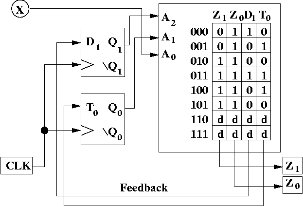
A few comments about the diagram above, in particular, the ROM.
In particular, z1z0 = 01 which is the output you get in state 00. D1 = 1 causes q1 to be 1 at the next positive edge. T1 = 0 causes q0 to stay at 0 at the next positive edge.
Thus, at the next positive edge, q1q0 = 10, which is the state we expect. If we're now in q1q0 = 00, on an input of 1, then we expect to be in state q1q0 = 10, at the next positive edge.
When the next positive edge occurs, and we're in state 01, then if x is still 0, then the address bits are AA1A0 = 100, which selects address 100.
This selects the 4 bit value at adress 100: z1z0D1T0 = 1101.
Thus, the output is now 11, which is the output you expect for state 10.
Try another state and another input to convince yourself this circuit works.
Recall from the Moore machine, you look at the current state, and then check what the output is from the FSM, and then copy the output bits for each occurrence of that state.
Here's an example of a Mealy machine. Notice the outputs are on the edges.

Here's the table. We've filled in the don't cares for rows 4 and 5, which correspond to state 10, which doesn't exist.
| Row | q1 | q0 | x | q1+ | q0+ | z |
| 0 | 0 | 0 | 0 | |||
| 1 | 0 | 0 | 1 | |||
| 2 | 0 | 1 | 0 | |||
| 3 | 0 | 1 | 1 | |||
| 4 | 1 | 0 | 0 | d | d | d |
| 5 | 1 | 0 | 1 | d | d | d |
| 6 | 1 | 1 | 0 | |||
| 7 | 1 | 1 | 1 |
Now, suppose you are in state 00, and see an input of a 0 (i.e., q1q0 = 00 and x = 0). At the next positive edge, you will go transition to state 11, and output a 1 (i.e., q1q0 = 11 and z = 1).
Suppose you are in state 00, and see an input of a 1 (i.e., q1q0 = 00 and x = 1). At the next positive edge, you will transition to state 01, and output a 1 (i.e., q1q0 = 01 and z = 1).
We can fill that information out in the table.
| Row | q1 | q0 | x | q1+ | q0+ | z |
| 0 | 0 | 0 | 0 | 1 | 1 | 1 |
| 1 | 0 | 0 | 1 | 0 | 1 | 1 |
| 2 | 0 | 1 | 0 | |||
| 3 | 0 | 1 | 1 | |||
| 4 | 1 | 0 | 0 | d | d | d |
| 5 | 1 | 0 | 1 | d | d | d |
| 6 | 1 | 1 | 0 | |||
| 7 | 1 | 1 | 1 |
As an exercise, you can fill out the rest of the chart yourself.
After that, the same steps are followed. Pick the flip flops, use the flip flop excitation table, and draw the circuit.
The ROM is convenient so we can design this part in a hurry, but in principle, all it takes is writing a sum of products expression for each of the columns.
The purpose of the ROM (or the circuit that would go in the place of the ROM) is to generate the correct control signals to the flip flops (using feedback) to get to the next state at the next positive clock edge, as well as to generate the output of the circuit.
However, it does take practice to be able to do it reasonably fast, and is difficult to understand conceptually, at least, at first. You should trace out a few steps just to convince yourself of how it behaves. There is a subtle difference in the behavior of the implementation of a Mealy and Moore machine. Tracing out a few steps can show the differences more clearly.
Usually, it's harder to understand why the circuit does the right thing (i.e., implements the FSM) than it is to know how to build it. Certainly, you should devote time to both understanding why this technique works, as well as mastering the technique.