Pipes
We claim that garbage would occur, even if two devices attempt to pump the same kind of soda (i.e., both red or both green). This probably doesn't happen in reality. That is, if two devices attempt to set the value of a wire to 1, the wire is most likely transmitting a 1 without problem.
Nevertheless, we want to avoid this situation. It should be the case that only one device writes a value to the wire, at any given time. There should be no reason for two devices writing to a wire or bus at the same time. Certainly, we expect devices to write to the wire at different times. The idea of a bus, after all, is that it is a shared medium of communication, to be used by all devices connected to the bus.
Controlling Registers
The outputs of registers are going to be connected to busses, and often there may be more than one register connected to a bus. We want to be able to control when a register writes a value to a bus.
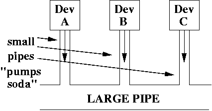
How can we do this? Let's think of our analogy. Suppose we have many small pipes hooked to a much larger pipe. For example, we might have 3 small pipes hooked up to a large pupe.
Suppose each small pipe is connected to a device which pumps soda. We want to make sure only one device is pumping soda into the large pipe. Unfortunately, each device is always pumping soda, which means all three devices are trying to pump soda.
If we can't turn off the device, how do we prevent the soda from being pumped into the large pipe?
One idea is to have some sort of device in the small pipe which can be opened or closed. When the device is closed, even though the device attempts to pump soda, it can't make it to the large pipe.
This device is usually called a valve. If the valve is open, soda can be pumped through. If the valve is closed, no soda can be pumped through.
Here's a diagram to illustrate the concept.
Introducing a Tri-State Buffer
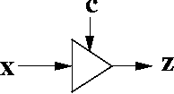
It looks very much like an inverter (a NOT gate) except it's missing a circle at the right side (where z is located). This tiny circle usually indicates that the device is inverting the input, x.
Unlike an inverter, a tri-state buffer has two inputs. It has a data input (labelled x) and a control input (labelled c).
When c = 1, the valve is open, and the output z is the same as the input x. Essentially, it lets the input value flow to the output. This input value can be 0, 1, Z, or ? (garbage).
When c = 0, the valve is closed, and the output z = Z, which means no electrical current (i.e., no 0's and 1's) is flowing through.
Regular Buffers
There are buffers which do not have a control input. Thus, the output is exactly the same as the input. It's the same as a tri-state buffer where c is always 1. Does that seem silly to you? The reason for such a device is to strengthen the signal. For example, when you make a phone call, the signal is sent over a wire, or perhaps a fiber optic cable.Over distance, a signal begins to lose strength. There are devices called repeaters which are meant to boost the strength of the signal. That's essentially what a plain buffer is.
However, we're interested in tri-state buffers, primarily because they behave like valves. They allow us to control which devices can write to a bus.
Chart for Tri-State Buffer
| c | x | z |
| 0 | 0 | Z |
| 0 | 1 | Z |
| 0 | Z | Z |
| 1 | 0 | 0 |
| 1 | 1 | 1 |
| 1 | Z | Z |
x is the data input. c is the control input, which turns on and off the valve. z is the output. Z (which is capitalized), means "no current", which, in our analogy, is "no soda" being pumped through.
A 32-bit Tri-State Buffer
We'd like to be able to use a single bit to control when, say, a register is allowed to write its 32 bit contents to a bus. If this bit is 1, then all 32 bits are written to the bus. If the bit is 0, then none of the bits are sent to the bus.
This can be easily implemented using 32 tri-state buffers.
The example below shows how to implement a 4-bit tri-state buffer using 4 1-bit tri-state buffers. It's easy to extend this idea to 32 bits.
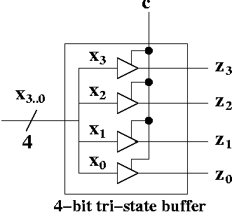
There is a bus containing 4 wires going into the "black box" (we get to see the inside of the black box) labelled x3..0.
Inside the black box, we split the bus into individual wires labelled x0 through x3. Each wire goes through a 1-bit tri-state buffer.
There's a single control bit c coming from the outside world, and this one bit is attached to each of the four tri-state buffers. So, either all four tri-state buffers let the input values go through or none of them go through.
As you can see, the implementation is pretty simple.
Summary
Usually, we use 32-bit tri-state buffers, which have 32 data inputs, 32 outputs, but a single control bit. The implementation is shown above.