A Review of MIPS Instruction Formats
Let's look at the three formats:
R-type Instruction
| Opcode | Register s | Register t | Register d | Shift Amt | Function |
| B31..26 | B25..21 | B20..16 | B15..11 | B11..6 | B5..0 |
| ooo ooo | sssss | ttttt | ddddd | aaaaa | ffffff |
- R-type instructions are short for "register type" instructions.
- Bits B31..26 are used for the opcode. For R-type instructions, the opcode is almost always 000 000. Normally, this makes no sense, because every instruction should have a unique opcode. However, bits B5..0 (the function part) uses 6 bits to specify the instruction. Only R-type instruction uses a function.
- Bits B25..21 specify a 5-bit UB encoding for the first source register.
- Bits B20..16 specify a 5-bit UB encoding for the second source register.
- Bits B15..11 specify a 5-bit UB encoding for the destination register. This specifies which register stores the result of the operation.
- Bits B11..6 specify the shift amount. This is usually 00000, except for shift instructions.
- Bits B5..0 specify a 6-bit function. Each R-type instruction has a unique 6 bit value. For example, add has a 6-bit value that's different from sub. add and sub are two different instructions.
I-type Instruction
| Opcode | Register s | Register t | Immediate |
| B31..26 | B25..21 | B20..16 | B15..0 |
| ooo ooo | sssss | ttttt | iiii iiii iiii iiii |
- I-type instructions are short for "immediate type" instructions.
- Bits B31..26 are used for the opcode. Unlike R-type instructions, the 6-bit value is NOT 000 000. There is no function code for I-type instructions.
- Bits B25..21 specify a 5-bit UB encoding for the source register.
- Bits B20..16 specify a 5-bit UB encoding for the destination register. Although this is called register t, instead of register d, it is treated as the destination register for I-type instructions.
- Bits B15..0 is the 16-bit immediate value. This may be a 16-bit UB number or a 16-bit 2C number. Notice that the immediate value is encoded directly into the instruction.
J-type Instruction
| Opcode | Target |
| B31..26 | B25..0 |
| ooo ooo | tt tttt tttt tttt tttt tttt tttt |
- J-type instructions are short for "jump type" instructions.
- Bits B31..26 are used for the opcode. Unlike R-type instructions, the 6-bit value is NOT 000 000. There is no function code for J-type instructions.
- Bits B25..0 are used for the offset. This is usually used to generate an address.
Notice that the J-type instruction has no source or destination registers.
Selecting Bits out of IR
In particular, we're going to want to look at the following subrange of bits.
- opcode IR31..26 All three types use
opcode.
- rs IR25..21 The first source register.
Used in R-type and I-type.
- rt IR20..16 The second source register
for R-type and the destination register for I-type.
- rd IR15..11 The destination register
for I-type.
- shamt IR10..6 The shift amount
for R-type.
- function IR5..0 The function for R-type.
- immediate IR15..0 The immediate value for I-type.
- offset IR25..0 The offset for J-type.
For any possible MIPS instructions, we can subdivide into 8 categories. Few, if any ISAs, can claim this.
Of course, you'll notice some overlap. For example, IR15 is a bit that exists in rd, immediate and offset.
However, that's OK. Recall that registers always output there values. For example, we might have a 4-bit register with z3..0. We can take one of the output bits, say, z1 and have three wires attached to it, and direct these three wires whereever we want.
So, to get IR15 to three different groups (i.e., rd, immediate and offset), we attach three wires to IR15 and send them to these three groups. It's that simple.
Here's a diagram.
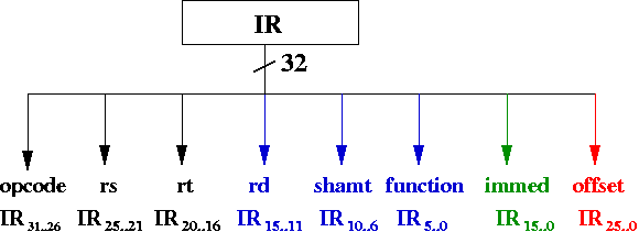
The arrow in blue refers to bits that only appear in R-type instructions. The arrow in red refers to bits that only appear in I-type instructions. The arrow in green refer to bits that only appear in J-type instructions. The arrows in black appear in two or more types.
Destination Register
First, it would match up better with the assembly language version of the instruction. For example, in add $r2, $r3, $r4 register $r2 is the destination register, yet rd is placed at bits IR15-11. Second, if we made bits IR25-21 refer to rd, then they would be the same for R-type instructions as well as I-type instructions.
However, this isn't the case.
- rd is the destination register for R-type instructions, and is located at bits IR15-11
- rt is the destination register for I-type instructions, and is located at bits IR20-16
This means we're going to need a 2-1 MUX to determine whether to use bits IR15-11 or IR20-16.
How does the CPU determine which group of 5 bits to pick? The CPU must determine whether the instruction is an R-type or an I-type. For MIPS, it can determine this from the opcode. What about the function bits? The CPU needs to distinguish between R-type and I-type using opcode bits alone. Think about why that must be the case.
There are 6 bits used for the opcode. That's 64 possible 6-bit bitstrings. We can program a ROM with 6 address bits. The opcode is then fed into the ROM. Each address contains 2 bits. Let 00 indicate the instruction is R-type. Let 01 indicate the instruction is I-type. Let 10 indicate the instruction is J-type.
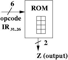
We can use the least significant bit of Z (the output of the ROM) to determine whether we have an R-type or an I-type. Notice that A0 = 0 for R-type and A0 = 1 for I-type.
You might ask "But what if it's J-type? Won't A0 = 0 and won't that be treated like an R-type instruction?". That would be true, except that we still have one more bit to control for the register file, namely, RegWrite. If we have a J-type instruction, then we can make sure RegWrite is 0, indicating we don't want to write to a register in the register file. Recall that J-type instructions don't even specify a register!
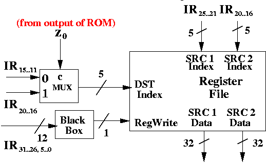
Here's a diagram that uses the output of the ROM (in particular, Z0, the least significant bit) to control a MUX deciding whether send IR15..11 (for R-type instructions) to DST index or IR20..16 (for I-type instructions).
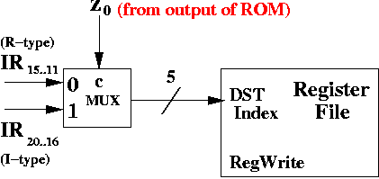
Recall that bits like IR20..16 come directly from the output of the IR (instruction register) through 5 wires. These are being fed into a 5-bit 2-1 MUX shown in the diagram above.
RegWrite is shown above, but we haven't attached any wires to it, yet. We will, soon enough.
Of course, we don't have to use a ROM. All we need is some combinational logic circuit that behaves equivalently to the ROM that takes in the 6 bits of opcode as input and produces a 2 bit result indiciating whether the instruction is R-type, I-type, or J-type.
By using a circuit, instead of a ROM, we have an opportunity to minimize the circuit. ROMs have one big drawback. They're large. Given k inputs, ROMS enumerate all 2k different results. This is comparable to having writing a cube function by having a very large array with the answers. Thus, you would look at cube[ i ] (assuming cube is an int array) for i3. That solution would be unnecessarily large. The same applies to hardware. However, for small number of inputs, ROMs are a simple solution.
Controlling RegWrite
Not all R-type or I-type instructions write to the destination register. For example, beq (branch equal) does not write any result to the register file.This time, we're going to need a circuit that takes 12 bits of input, 6 bits from the opcode and 6 more bits for the function bits. Why do we need the function bits? Nearly all R-type instructions (if not all) have the opcode as 000 000. In other words, the function bits specify what kind of R-type instruction we're going to execute. Some of those may write to a destination register, some may not.
So, we can build a combinational logic circuit with 12 bits of input and 1 bit of output to determine whether RegWrite should be 0 (don't write) or 1 (write).
We'll just put in "black box" in our diagram for our combinational logic circuit.
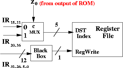
Notice that we write IR31..26, 5..0 to indicate the 12 bits used as input to the black box. These are the opcode bits (IR31..26) and the function bits (IR5..0). The function bits are ignored by the black box when it's an I-type or J-type instruction.
Source Registers
Here's how it looks:
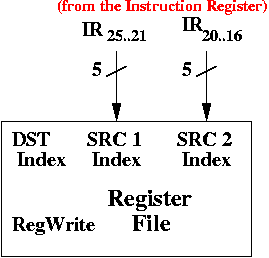
The rest of the wires, etc., have been left off (e.g., DST Index and RegWrite inputs) to make the diagram less cluttered. They're still there, but we're just not drawing it.
You might ask why rt bits are being sent to SRC 2 Index. After all, they're not used for I-type instructions (rt is sent to the DST Index bits for I-type instructions), and they aren't used in J-type instructions. So, at least part of the times, the bits sent to SRC 2 Index are nonsense. During those times, we don't really want the contents of the register specified by the bits from SRC 2 Index.
That's OK. It turns out we can ignore SRC 2 Data (which is the register contents specified by SRC 2 Index, and is output by the register file) if it isn't an R-type instruction. In fact, we do ignore the output when it's not R-type instruction.
Operand Fetching
The instruction contains information about the destination registers. For R-type, those bits are IR15..11. For I-type, those bits are IR20..16. I don't know why they didn't simple make IR25..21 the destination register, but they didn't. It doesn't make that much sense to me.
Summary
MIPS, in particular, divides instructions into 3 categories: R-type, I-type, and J-type. This means we can already fetch rs and rt (i.e., SRC 1 Index and SRC 2 Index even before we know what instruction we have).
Here's a diagram of all the bits used between the IR and the register file:
There are still a few things missing from the diagram:
- DST Data is missing
- Where SRC 1 Data and SRC 2 Data go to is not shown.
However, you can see that the output bits from the instruction register are used to select source and destination registers. The opcode and function is used to control which bits are sent to the DST Index.
In the next step, we're going to see how to perform computation on SRC 1 Data and SRC 2 Data.