Control Signals
Let's look at the kinds of control signals various devices have:
| Device | Control Signals |
| MUX | One of x0,...,xn-1, written in base 10 |
| Register | Regload (if we write this signal, then parallel load this register. If it isn't written, perform a hold) |
| ALU | Operations for add, sub, etc, |
So far, we only have three kinds of circuits. There's two of them that are combinational logic: the MUX and the ALU. There's one that's sequential: the registers.
Let's talk about each one.
MUX
A MUX selects one of k data inputs. The control bits determine which input is directed to the output. There are ceil( lg k ) control bits, which we treat as a ceil( lg k )-bit UB number.Usually, we'll label the MUX with a name. For example, we might have an MDRmux. To indicate which input we're selecting, we write the input number in base 10.
For example, suppose we have 4 possible inputs for 4-1 MUX called FOOmux. We can write one of: FOOmux = 0, FOOmux = 1, FOOmux = 2, or FOOmux = 3, depending on which input we want to pick.
We'll always specify the control signal for a MUX and its value. For other control signals (in particular, registers, which are discussed in the next section, we may not always write the control signal for registers).
Registers
A parallel load register supports two operations: parallel load and hold. The typical operation is to hold.To emphasize that point, we'll only put a control signal for a register when it is loading. For example, suppose we have a register, PC. If we write PCload, this means that we've sent a signal for the PC register to perform a load. If we don't write PCload, this means the PC register holds its value.
ALU
The arithmetic logic unit (ALU) can perform different operations. Normally, the ALU has a list of operations associated with a binary code. Here's a small example:
| Code | Operation |
| 00 | Z = X + Y |
| 01 | Z = X - Y |
| 10 | Z = X & Y |
| 11 | Z = ~X |
Normally, an ALU has many more operations than this, but this gives you an idea of how to associate a bitstring with an operation.
In order to indicate with ALU operation, we want, we'll write it in English. Thus, we'll write ALUop = add. To be accurate, we should say ALUop = 00 which is the 2 bit code (listed above) for performing an add. However, this would force you to look at the chart all the time. It's easier to write and understand ALUop = add. All you have to do is to realize that there's some bitstring associated with add, and not worry exactly what it is.
Tri-State Buffers
We'll give each tri-state buffer a unique name. For example, one name might be MARout. The name has out as a subscript.If the name of the tri-state buffer control signal, e.g. MARout, appears in a state, that means the tri-state buffer is active, and the input values are flowing to the output.
If the name does not appears in a state, then the tri-state buffer is inactive, and no data is flowing from input to output.
Register Transfer Language (RTL)
Individual statements in RTL usually look like:
R1 <- R2 + R3 # R1 gets R2 + R2
A typical statement has a register on the left-hand side of a left
arrow. Think of the left arrow as an assignment statement. In reality,
we want to perform a load. It just happens to look like an assignment
statement.
The main reason we call it "register transfer" language is because the statements involve transferring and operating on data, and eventually loading it in some register. In a CPU, data moves around and is operated on.
Not every RTL statement is valid. You have to look at the "datapath" of the CPU and the control signals, to see whether an operation can be performed or not.
Moving and operating on data is similar to charting a path for someone to perform errands. You might, for example, have someone go pick up cereal, then drop off dry-cleaning, then go to the bookstore, and stop by a bank. Ass
Assuming you tell the person the exact path (just like you might see in Yahoo Maps or MapQuest), you need to make sure the sequence of roads is correct. You don't want to say to get from point A to point B without a road connecting the two locations. If a person is supposed to pick up cereal, there should be a store for them to pick it up.
Similarly, the datapath of a CPU has restrictions. Ideally, you want to do as much in parallel as possible. However, the datapath and controls may force you to do things in steps.
For example, suppose you have four parallel load registers hooked up in a row.
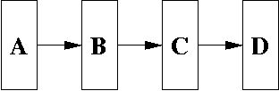
Suppose you wanted to perform the following RTL statement.
D <- A
That is, you want to have register D loaded with the contents
of register A.
You can't do this in a single RTL statement. There is no direct path from A to D.
However, you can write three consecutive RTL statements, as in:
  B <- A

  C <- B

  D <- C
These three RTL statements have to be run in consecutive clock
cycles. You can't do all three at the same time. Thus, on the first
clock edge, you run B <- A. Then, on the next clock
edge, you run C <- B. Finally, on the next clock edge,
you run D <- C.
Recall that at a clock edge, a register can perform a parallel load. If it does so, the register reads in the input, and a short time later, it has latched onto this value, and then this value is asserted on the output. In other words, it takes some time after the clock edge before the input goes to the output. It doesn't take too much time, but it isn't instantaneous either.
Thus, at the first clock edge, register B reads its input, which is the output of register A. Let's assume register A contains the value 10. So register A outputs 10. Since register A's output is fed into the input of register B, then register B "sees" input 10. Until the clock edge occurs, register B doesn't load the value.
Once the edge occurs, register B loads the value 10. After a short amount of time, the output of register B is 10.
However, by the time B outputs 10, register C, which saw the positive edge at the same time register B did, and so register C has loaded the old value of register B. Let's say that was 0. Thus, register C doesn't see the 10 in its input value (which is register B's output) until after the positive clock edge has occurred.
That turns out to be a good thing because it would be hard to reason about how the registers' values are changing if it weren't this way. It makes sense that at a positive edge, a register can only read in the value of its immediate input, and not the value of some other input with a register in between. Thus, register C can't load register A's value.
Finite State Machines (FSMs)
However, instead of using a programming language like C, we're going to use a finite state machine. Finite state machines are basically a kind of crude programming language. In general, you wouldn't really program with them, for general purpose programming. However, for coordinating control signals, they do a good job, and it's fairly easy to convert a finite state machine to a circuit using flip flops and combinational logic gates.
You might wonder how RTL fits in all of this. RTL is a higher-level language than FSMs. Think of it as an outline of what we need to do. RTL only describes how data moves from one location to another and what operations are performed. It doesn't describe the control signals needed to perform the operation.
Black Box
Once implemented, we can think of an FSM as some black box, consisting of inputs (data and control), outputs, and a clock. At each positive edge of the clock, the input is read in, processed, and the outputs updated.
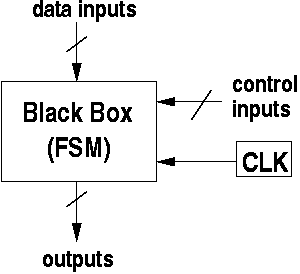
What's happening inside the box? A sequential machine contains some internal state. State can be implemented using k-bit control register inside the black box for some appropriate value of k.
At this point, we're going to use the black box as a control unit. In a CPU, the control unit sequences the control signals to control when registers should load, which input should be selected on a MUX, and which operations should be performed by the ALU.
The outputs of the control unit are hooked up to the control bits of each of these devices.
Here is a more precise behavior of what happens in the control unit, which is a FSM.
- Clock generates positive clock edge.
- Inputs are read in by the control unit.
- Control unit does some computations to determine which state to go into.
- Control unit goes into new state, generating outputs associated with the new state.
Notice that the control unit requires information about the outside world through its inputs. These inputs come from several places. One of the places is the instruction register. The control unit needs to know what instruction is being executed in order to determine what to do. Also, the control unit needs status bits from the ALU to determine what has happened to a computation. For example, it can use this information to decide whether to branch or not.
The Clock
Here's a timing diagram for the clock we're going to use.
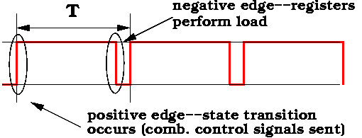
- On a positive edge, we go into a (potentially) new state in the control unit FSM. When we enter the new state, control signals are sent to the various devices. Combinational logic devices such as the ALU and MUX respond right away.
- Registers in the CPU (but not in the control unit itself) use the negative edge. Thus, if a load occurs, it occurs on the negative edge.
Notice that we are using both the postive and negative edge. Also, notice how long the clock stays at 1. I've drawn the diagram so that it stays at 1 for 7/8 T. The exact fraction is unimportant. The goal is to keep the clock's value at 1 long enough for the ALU and MUX to perform their operations and have their outputs valid, before any loads are performed on registers.
This is the reason we're using two edges of the clock. When the control signals are updated on the ALU and MUXes, it takes some time before the output of those combinational logic devices is valid. We need those devices to complete their operations before registers can load.
Books usually skip this part because it's a bit subtle to explain the small amount of time needed for operations to complete before loading. However, it's not that hard to understand, and I think it's important, so I'm including it here.
A Small Example
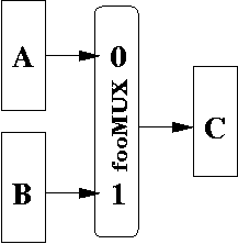
Suppose we wanted to perform two RTL operations.
  C <- A

  C <- B
Each operation corresponds to the following control signals
  C <- A
     fooMUX = 0
     -----------
     Cload
  C <- B
     fooMUX = 1
     -----------
     Cload
Let's consider the first set of control signals:
  C <- A   # RTL in black.  Control signals in red
     fooMUX = 0
     -----------
     Cload
Above the line, we put control signals to MUXes and ALUs, i.e.,
basically any device that is not a register. These signals are
active at the positive edge of the clock.
Below the dashed line, we put any register loads. In this case, we have Cload, which means that we perform a load. Notice that register A and B do not appear. Since they do not appear, those registers are performing hold operations.
In this state, the control signals cause the fooMUX to be set to 0. This means that register A's output is sent to the output of the MUX, which is sent to the input of register C. When the negative edge arrives, register C loads in register A's value.
As you can see, the RTL does not describe what happens to the fooMUX. However, the signals in the state do.
The second set of control signals look like:
  C <- A   # RTL in black.  Control signals in red
     fooMUX = 1
     -----------
     Cload
The only difference is that the fooMUX is set to 1. This
sends register B's output to the output of the MUX, which is
sent to the input of register C. When the negative edge
occurs, register C parallel loads the input value, which is
the value of register B.
As you can see, RTL is primarily concerned with data movement, but doesn't describe the control signals to make it happen. We write the control signals underneath the RTL statement. The control signals below the line are the register loads. The remaining control signals above the line are usually control bits of combinational logic devices and tri-state buffers.
Parallel Operations
In the example above, we could only basically do a load of register C. Suppose that register A had some inputs coming from somewhere else, say, register Z. We could perform Aload and Cload at the same time.
For example:
C <- A || A <- Z
This says to simulataneously parallel load register C and
register A. Basically, the way you do this is to look at the
old value of A and Z and then update the registers,
C and A, respectively, with this old values.
In other words, you DON'T want to load Z into A (thus updating A), followed by C loading the new value of A (which is Z). Since this is done in parallel, you want to have C to load the old value of A (i.e., its value before Z was loaded).
Thus, it's possible for two RTL statements to execute at the same time, provided the circuit's datapath permits it. One way we can write this is to put the double vertical bars, ||, between RTL statements that can be executed in the same state. The || reminds us that it can be done in "parallel" (since they are parallel symbols).
Conditional State Transitions and Loops
This is how it works. Each state has a list of control signals. It also has a conditional statement that allows you to transition to other states.
Here's an example:
State 1:
   # Control Signals
   CE = 1
   R/\W = 1
   MARout
   # State Transition
    ACK == 1 -->  goto State 2
    ACK == 0 -->  goto State 1
In this example, we are in a state which we've labelled as State 1.
This state generates several signals: CE = 1, R/\W = 1,
and MARout (this turns on the tri-state buffers). Normally,
a state generates a register load, but in this case, it doesn't.
The code at the bottom is basically a switch statement. Left of the arrow is a condition (also called a guard) which is either true or false. If it's true, then the statement to the right of the arrow is executed.
Based on the value of input signals (in this case, ACK), it may transition to State 2 or it may stay in State 1.
Traditional FSMs
The purpose of a traditional FSM is to determine whether a string is in a language or not. A string consists of characters of the alphabet. The alphabet is a mathematical construct. It can be real letters of a real alphabet, or it can even be digits. Basically, an alphabet just a finite set. A string is an ordered set of "characters" from this alphabet.
A traditional FSM processes the string one character at a time, and moves from one state to the next. If, after processing the last character of the string, the finite state machine is now in a final state, then the string is accepted (which means it's part of the language), if it's not in a final state, then the string is rejected (which means it's not part of the language).
This may seem like a weird kind of machine. It's purpose is to recognize some kind of mathematical language. It's not even a real, physical machine (although it could be).
Our FSM is a little different. In particular, we have no set of final states. However, we do have output. Each state is associated with some output.
In our implementation of an FSM, we perform a state transition at each clock edge. We don't have to always go to a new state when an edge occurs.
Instead of recognizing a language, our FSM is used mostly to sequence control signals.
Summary
RTL (register transfer language) is used to describe data movement in the CPU, primarily by indicating which registers get loaded with which values.
A RTL statement is a statement with a register on the left hand side, being loaded by some value usually due to some computation performed on one or more registers on the right hand side. A valid RTL statement is one that can be executed on a particular circuit layout in one clock cycle. The validity of an RTL statement depends on the datapath of the circuit. The datapath is the layout of the circuit, indicating where values can go.
More than one RTL statement can be executed in parallel, assuming the datapath permits it.
An RTL is then implemented by a series of control signals. These control signals are the values output by a particular state. We can design an FSM that implements the RTL, where each state describes what output signals are asserted.
The FSM uses inputs (from the outside world) to determine what state to transition to.
We'll see more details of how all this works in future notes.