Thinking it Out
Let's define what those terms mean:
- load To "load" means to copy a value from memory at some
memory address, to a register. The value might be a word (32 bits),
halfword (16 bits) or byte (8 bits). If the value is any shorter
than a word, then it may be loaded as signed (where the value is
sign-extended to 32 bits) or unsigned (where the value is zero-extended
to 32 bits).
- store Store is the opposite operation of load. Where load copies a value from memory to a register, store copies a value from register to memory.
MIPS, like many RISC ISAs, is often called a load-store architecture. That means that the only operations that interact with memory (for data) are load/store instructions. The goal is for many instructions to primarily operate on registers. This is easier to do now because RISC ISAs use many registers. Older CPUs often had between 1-4 registers to use, and so using memory data for operands was more important. With 32 or more registers, most RISC ISAs can load data to registers, and perform operations only on the registers.
When you realize that it can be 100-400 times slower to access main memory (RAM) than registers, you can see why we would prefer to use registers, when possible.
Now let's think about what it would mean to load data from memory.
Here's a typical load instruction.
ld $r3, -10($r10) # Effective address is Reg[ 10 ] - 10
The effective address is the address where we're going to load
the word from. It's computed by taking the contents of the register in
the second operand, and adding the offset. In this case, the register
is $r10 and the offset is -10.
You load a word (i.e., four consecutive bytes) from that address into the destination register. In this example, it's $r3.
Think about the only operation we've used that has accessed memory. We've fetched instructions.
The only thing that's going to be different about fetching instructions and loading a word is where the address is generated. For fetching instructions, you use PC. For loading a word, it's adding the contents of the register plus the offset.
Where is the that sum computed? From the ALU. So, the output of the ALU eventually generates the sum of the register plus the offset (i.e., the immediate value).
We need to put that result into the MAR. Thus, we need to have two different ways to load the MAR: the PC (for placing the instruction address) and the output of the ALU (after we've computed the effective address).
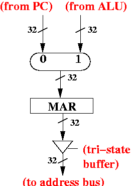
After we have address in the MAR, we can fetch the data at that address. At that point, it's just like fetching an instruction. We can place the fetched word into the MDR.
Getting Rid of the MDR
We can save one clock cycle if we load either the IR or the destination register directly from the data bus.
So, that's what we're going to do. The diagram looks like:
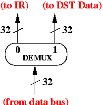
We're using a demultiplexer. Either we can pick output 0 and send the data to the instruction register (when the CPU fetches an instruction) or to the DST Data input of the register file (when the CPU is loading a word). We may need some circuitry to sign or zero extend the result if we are only fetching a halfword or byte.
What happens if we're not fetching an instruction nor loading a word? There's a load signal for IR as well as a RegWrite for the register file. If both are false, then no data is loaded, regardless of what the DEMUX control input is set to.
Thus, the DEMUX is always sending the data bus data to either the IR or the DST Data, but they could both be ignoring the data. This is good because most of the times, the data of the data bus is garbage, and we don't want to load it to IR or the register file.
store
A read operation is sent to memory. Memory eventually places the data onto the data bus, and sends an ACK signal back to the CPU. At that point, the data is read off the data bus. It is directed by the DEMUX either to the IR or to the register file.
However, for a store, we need to send the data a different way. In particular, instead of reading the data from the data bus, we need to send it to the data bus.
Where do we get the data from? Let's look at a typical store
instruction.
sw $r3, -10($r10) # Effective address is Reg[ 10 ] - 10
We need to do two things. First, we need compute the effective
address. This requires that we send rs (which is $r10
in the example) to the X input of the ALU. We also send
the immediate value, -10, to input Y (this is done by taking
IR15..0 through the zero/sign extender, and sign
extending it to 32 bits), and selecting input 1 of the Y MUX
(see the diagrams in the notes about the ALU, to remind yourself what
the ALU looks like).
However, we also need $r3. Recall this is really rt. rt is already being fed into the register file and it's being output as SRC 2 Data. However, right now the MUX is selecting input 1, not input 0. This means that SRC 2 Data is being ignored by the ALU.
However, we don't need the ALU to process SRC 2 Data. We can use that data directly, and send it to the data bus.
This is what the diagram looks like:
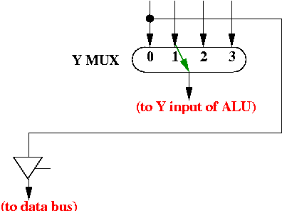
Let's look at the key aspects of this diagram.
- store operation is being performed
- For the Y MUX,Input 0 is SRC 2 Data. Input 1 is IR15..0 sign or zero extended to 32 bits. Input 2 is IR15..0 sign-extended and shifted to the left 2 bits. Input 3 is the hardwired constant +4
- For a store operation, input 1 is selected by the MUX so the effective address can be computed. There's a green arrow to show this.
- A bus (32 wires) is hooked to SRC 2 Data (also input 0 of the Y MUX) and routed to the data bus. We use a 32 input tri-state buffer to make sure that we can control when this data appears on the data bus.
Why it's rt
Earlier on, I questioned why rt is the destination register for I-type instructions. It seemed strange because rd seems the better choice. However, the answer is now clear. rt is needed for store operations.Suppose rd was the destination register. The rd bits (from IR) is connected to DST Index. This would work well for load instructions and many other instructions. What about store?
store is the only instruction that requires two sets of outputs:
the data to be stored, and the address to store it at. In the
instruction
sw $r3, -10($r10) # Effective address is Reg[ 10 ] - 10
$r3 is the rt and rt is always fed into SRC
2 Index. Even though this is an I-type instruction and
even though we usually ignore SRC 2 Index in an I-type
instruction, this is the one rare (but important) case where we use
both the immediate value and rt.
Summary
Performing a store is somewhat different. It requires accessing the destination register, while at the same time computing the address of memory in store. This is done by having the SRC 2 Data output directed to the data bus.
Finally, we've been able to do away with the MDR by using a DEMUX from the data bus to either the IR or the DST Data of the register file. By doing away with the MDR, we can save one clock cycle. With the MDR, we needed one clock cycle to get the data off the data bus into the MDR, and one more clock cycle to move it from the MDR to other parts of the CPU.