A n-1 multiplixer, or MUX, for short, is a device that allows you to pick one of n inputs and direct it to an output.
Many devices are essentially multiplexers. Think about a remote control for a TV. You select one channel, and that one channel is displayed on your screen. Similarly, you select a radio station to listen to, and it plays on your radio.
An n-1 MUX consists of the following:
where ceil is the ceiling function ( ceil(x) = n for the smallest integer where n >= x).
Given n possible choices for inputs, you need log2 n bits to select it (technically, you need the ceiling of this, just in case n is not a power of 2).
For example, if you have 16 possible inputs, you need 4 bits to specify one of 16 values. If you have, say, 12 possible inputs, you still need 4 bits, even though some of the 4 bit patterns may not correspond to any of the 12 choices.
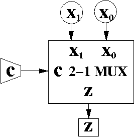
If c == 0, then x0 is directed to the output z. If c == 1, then x1 is directed to the output z.
| Row | c | x1 | x0 | z |
| 0 | 0 | 0 | 0 | 0 |
| 1 | 0 | 0 | 1 | 1 |
| 2 | 0 | 1 | 0 | 0 |
| 3 | 0 | 1 | 1 | 1 |
| 4 | 1 | 0 | 0 | 0 |
| 5 | 1 | 0 | 1 | 0 |
| 6 | 1 | 1 | 0 | 1 |
| 7 | 1 | 1 | 1 | 1 |
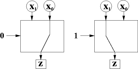
The first four rows have c == 0, so they select column x0. The second four rows have c == 1, so they select column x1.
We can shrink the number of rows by creating a condensed truth table which modifies truth tables in the following way:
| Row | c | z |
| 0 | 0 | x0 |
| 1 | 1 | x1 |
We think of the control bit as a 1 bit number. Thus, c == 0 or c == 1. The control bit selects the input with the same value as the control bit. Thus, when c == 0, we select x0 (notice the subscript has the same value as the control bit). When c == 1, we select x1 (again, the subscript has the same value as the control bit).
Let's apply this rule. In the truth table above, both rows have a non-zero output. Row 0 has output x0, and row 1 has output x1.
We create a modified minterm for each row:
The minterm for row 0 is normally \c, but we AND that with the output x0 to get \cx0.
Then, we OR the two modified minterms to get the output:
z = \cx0 + cx1
This is not the same result you would get if you were simply doing sum of products on the non-condensed truth table.
However, I think this version is easier to understand. Remember the one fact about minterms. Given a specific set of values, at most one minterm is true. Thus, either \c == 1 (equivalently, c == 0) or c == 1. When one minterm is 1, the other minterms are 0.
Thus, when c == 0, we get:
  z = \cx0 + cx1
    = 1 x0 + 0 x1
    = x0
When c == 1, we get:
  z = \cx0 + cx1
    = 0 x0 + 1 x1
    = x1
So, you can see that we select one of x0 or x1 and zero out the other term.
This time, we think of c1c0 as a 2 bit number. When c1c0 = 00, we select x0 (since 002 is 0 in base 10). When c1c0 = 01, we select x1 (since 012 is 1 in base 10). When c1c0 = 10, we select x2 (since 102 is 2 in base 10). When c1c0 = 11, we select x3 (since 112 is 3 in base 10).
Here's the condensed truth table.
| Row | c1 | c0 | z |
| 0 | 0 | 0 | x0 |
| 1 | 0 | 1 | x1 |
| 2 | 1 | 0 | x2 |
| 3 | 1 | 1 | x3 |
Again, create a modified minterm for each row with a non-zero output.
The Boolean expression for a 4-1 MUX is:
z = \c1\c0x0 + \c1c0x1 + c1\c0x2 + c1c0x3
Since you're only selecting one of two inputs, you use only one control bit, even though each input is more than one bit.
Here's a diagram for how to do this.
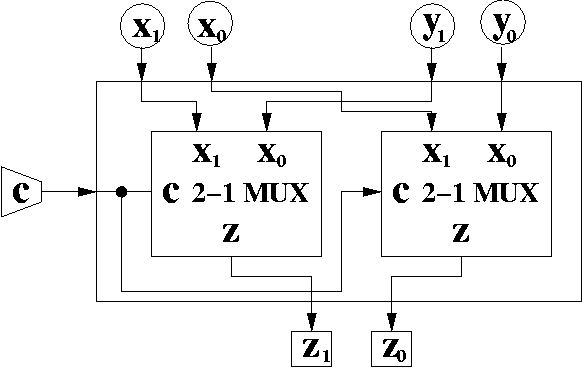
The left MUX is used to select either x1 or y1, while the right MUX is used to select either x0 or y0.
In order to understand this circuit more fully, you may wish to "trace" to see what happens to the inputs when c == 0 and when c == 1.
Here's the diagram.
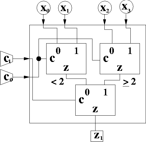
This diagram is a little complicated to understand. Here's the idea. If c0 == 0, then the two bit number c1c0 is even (since even numbers in binary end in 0). If c0 == 1, then the two bit number c1c0 is odd (since odd numbers in binary end in 1).
The top two MUXes have their control input hooked up to c0. This either picks x0 and x2 if c0 == 0 (it picks the inputs with even indexes). Or it picks x1 and x3 if c0 == 1 (it picks the inputs with odd indexes).
The bottom MUX then uses c1 to determine whether it should pick the larger of x1 and x3 or whether it should pick the larger of x0 and x2.
This is a circuit that you should try to trace through all four possible values of c1c0 to see what is happening. Again, realize the upper two MUXes select even or odd indexes, and the bottom MUX selects the index greater than or equal to 2, or indexes less than 2.
To see if you really understand this, try implementing the circuit where c1 must be hooked to the top two MUXes while c0 is hooked to the bottom. Determine how the inputs must change to accomodate this.
Also, implement an 8-1 MUX out of 2-1 MUXes.
Notice that we have 3 control bits. That's because ceil( log2 5 ) = 3. However, with 3 bits, we can specify 8 possible inputs. We only have 5. What do we do with the other 3?
One reasonable answer is not to care. That is, as long as the control inputs have values 000, 001, 010, 011, and 100 and it produces the correct output for those inputs, then that's all that matters. The MUX can produce incorrect output for 101, 110, and 111 since those values are undefined.
As an exercise, build this circuit using only 2-1 MUXes and 4-1 MUXes. Trace your result to see that it works properly.
An 1-n DeMUX consists of the following:
In a MUX you have one of n inputs to choose from and direct to an output. In a DeMUX, you have a single input, but one of n outputs to choose from to direct the input.
Think of a DeMUX like a mailroom. You have many pieces of letters coming in, and you must distribute each letter to one of many different mail boxes.
Even though DeMUXes act like the opposite of MUXes, MUXes seem much more useful than DeMUXes.
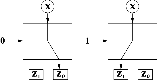
When c == 0, the input, x, is directed to the output z0. When c == 1, the input, x, is directed to the output z1. Just as before, we think of c as a 1 bit number, which specifies the output we want to direct the input to.
As before, the condensed truth table only uses control bits for the input portions of the truth table, and allows data input variables to appear in the outputs.
| Row | c | z0 | z1 |
| 0 | 0 | x | 0 |
| 1 | 1 | 0 | x |
We can write a Boolean expression for z1 and z0. The rules for creating Boolean expressions for condensed truth tables are the same as before:
This is fairly easy, because each output variable only has one non-zero row.
Thus,
  z1 = c x
  z0 = \c x
DeMUXes are less important, but still useful. They are essentially MUXes where the data inputs are switched with the outputs. As with a MUX, a 1 to N DeMUX uses ceil( lg N ) control bits.