If you have this kind of problem, which is essentially to design a function, then you can use a decoder-encoder trick to quickly implement this.
Here's how the mapping looks:
| Base 10 Value | SM Representation | 1C Representation |
| -3 | 111 (7) | 100 (4) |
| -2 | 110 (6) | 101 (5) |
| -1 | 101 (5) | 110 (6) |
| -0 | 100 (4) | 111 (7) |
| 0 | 000 (0) | 000 (0) |
| 1 | 001 (1) | 001 (1) |
| 2 | 010 (2) | 010 (2) |
| 3 | 011 (3) | 011 (3) |
In parentheses, you will see the value of the bitstring interpreting the bitstring as a UB value. Why UB? Encoders and decoders assume their inputs are in UB.
For example, while 111 is -3 in SM and 100 is -3 in 1C, they are 7 and 4 respectively in UB. Thus, we need to create a circuit that maps 7 to 4. The person using the circuit never has to know about that UB was the representation, but the person designing the circuit does need to know it.
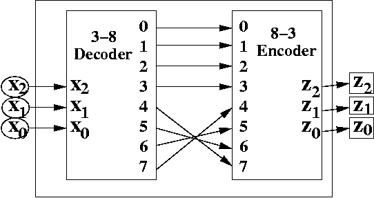
The best way to understand this circuit is to trace it. For example, suppose 111 comes into the circuit. Then, z7 is 1. This gets fed into x4. Out comes 100. Thus, we have the mapping from 111 to 100, which is the correct conversion from SM to 1C.
You might notice that we mapped negative 0 to negative 0 (i.e., 100 to 111). Both SM and 1C have two representations for zeroes. However, they can be thought of as the same value (namely, zero).
So, it would be perfectly valid to map, say, 100 (SM) to 000 (1C), or even 000 (SM) to 111 (1C). While the mapping may be more "accurate" the way it's done above, it's always good to realize you are (in principle) mapping one representation to another by the value it represents, and that having two zeroes is a quirk of the representation. That is, we really should not distinguish between a negative and positive 0. They both map to the same value of 0.
However, you should not hook up both z0 and z3 to x4. This violates one of the rules of combinational logic design. Two outputs can not hook to the same input. This will cause their signals to interfere, and may lead to incorrect inputs read in.
Furthermore, in designing a circuit that implements a function, you may leave certain inputs of the encoder unattached. That also violates a rule of combinational logic circuit design.. If a circuit has, say, 8 inputs, there should be 8 inputs. Do not leave any input unattachess s If necessary, use hardwired 0's or 1's to fill those inputs as appropriate.
It shouldn't take you too long to figure out what to do if you have a function, instead of a permutation (which is a specific kind of function).
As usual, this is considered a "trick", meant to allow you to answer questions on exam quickly. It may not be the best circuit to use if you're concerned about minimizing gates.