Register File as a Black Box

Introduction

We're beginning our venture into learning how a computer really works. A computer essentially executes instructions. But how does it do this? What are the pieces of hardware involved? What is the sequence of actions get performed to execute an instruction?

An important component of running instructions are the registers. As you should know by now, registers are located on the CPU. Registers are very fast memory components. They are much faster than RAM.

This begs the question: why use anything besides registers? Why not have a billion registers and be done with it?

Here's the way to understand memory. If you want more memory, it will be slower to access, but cheaper. As you get more and more registers, you will find it difficult to make them fast, and to keep them as fast as possible will be expensive.

To make it easier to understand registers, we will put them in a black box called a register file. If we didn't do this, there would be a lot of wires to draw, and you would find it very difficult to understand.

We place the 32 integer registers inside a black box. That black box is called a register file.

To design the register file, we'll go through two steps. This will make it easier to follow its construction.

Reading from a Register File

Imagine that we want to run the following instruction:
  add $r1, $r2, $r3  # R[1] <- R[2] + R[3]
What are the individual steps needed to make this happen? To perform the addition, you need the values of registers 2 and 3.

We need to fetch the operands, i.e., the values of register 2 and 3, from the register file. So, what do we need to tell the register file? We need to tell it which registers we want.

There are 32 registers in the register files, so one way to identify the registers is by a bitstring. Recall that labeling N items requires ceil( lg ( N ) ) bits. In this case N is 32. Thus, to label 32 registers, you need ceil( lg( 32 ) ) = 5 bits. We identify the registers using 5 bit UB. Therefore, 00000 represents register 0, and 11111 represents register 31.

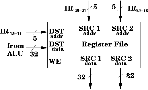
We want to access two registers, so we need 10 bits of input. So, the register file should have SRC 1addr, which is a 5 bit input "address" to indicate the first source register, and it should have SRC 2addr, which is another 5 bit input, to indicate the "index" or "address" of the second source register.

In our example, those 10 bits would be 00010 and 00011, which indicate registers 2 and 3, respectively.

But where should the bits come from?

We know, by now, that a CPU contains some hidden registers. In particular, there's a register called IR (short for instruction register). That register stores the instruction currently being executed.

If we're executing the instruction, add $r1, $r2, $r3, we can access the bits for the register directly from the instruction itself. In particular, $r2 is stored in bits B25-21 (which is the rs register) and $r3 is stored in bits B20-16 (which is the rt register).

Here's the encoding for add $r1, $r2, $r3,

Register s is the first source register. Register t is the second source register. Register d is the destination register. Recall that in the instruction add $r1, $r2, $r3, $r1 is the destination register, while $r2 and $r3 are the two source registers.

This is one reason good ISA design helps. Since we know the layout of an R-type instruction, we can get the desired bits for the source registers without doing (much) decoding.

Once the ten bits are sent from the IR as inputs to the register file, the register file produces 64 bits of output. We specify 5 bits for the index of the first source register, and it outputs the 32 bits which are the contents of that register. We also specify 5 bits for the index of the first source register, and it outputs the 32 bits which are the contents of that register.

There is a small delay from the input addresses (indexes) being read in by the register file, until the outputs (contents of the register) are produced by the register file.

Here's a diagram of the register file so far.

Writing to a Register File

Reading from a register file is only half the story. We also need to modify registers in the register file. This is where we can take our cue from memory.

With memory, we need the ability to read from memory and write to memory. To distinguish between which operation we want to do, we have the control pin, R/\W. When R/\W = 1, we tell memory that we want to read from memory. When R/\W = 0, we tell memory that we want to write to memory.

It turns out that we'll only read from the register file as shown in the previous section. We'll have additional inputs to the file to write to the register file.

Thus, we'll use a control input called WE for write enable. When WE = 1, then we want to write to the register file. Otherwise, we don't write to the register file at all. Of course, we'll need to specify which register to write to (we don't want to write to all registers).

To see how we should set up the register file for writing, consider the instruction again.

  add $r1, $r2, $r3  # R[1] <- R[2] + R[3]
Once we add R[2] to R[3], we need to save the result to a register, namely R[1]. This is the destination register.

Each instruction can, at most, update one register---the destination register.

We need the ability to specify the index of the destination register to the register file.

Like the source registers, we require 5 bits to indicate the destination register. Also, like the destination register, these 5 bits can come from IR. In particular, bits B15-11 are the bits used for the destination register in an R-type instruction. These bits are inputs for DSTaddr.

Also, we need 32 bits of data to write to the register. So, this is DSTdata. The data comes from the output of the ALU.

Register File Is Oblivious

Even though we say the address inputs come from the instruction register, in particular, bits B25-21 (source 1), B20-15 (source 2), and B15-11 (destination), at when it's an R-type instruction, and the DSTdata comes from the ALU, it doesn't have to be this way.

The register file is a black box. It doesn't matter where the inputs are coming from or where the outputs are going to. It helps our understanding to know where the inputs come from or where the outputs go to, but the register file behaves the same regardless.

This emphasizes our view of hardware. We deal in black boxes. These are basically like functions from any programming language. They accept input. They produce output.

Of course, it makes sense for those bits to come from the IR, since that's where the information is located.

Here's how the register file looks now.

You might wonder why there's no chip-enable. It turns out that it's OK to leave the register file in "read-mode", i.e., reading the values of the two source registers. The rest of the hardware can ignore the output data coming from the register file, if need be.

Summary

The register file is a convenient way to describe a set of registers. We treat the register file like a black box. In particular, the register file has the following inputs:

It also has the following outputs

Web Accessibility

Opcode Register s Register t Register d Shift Function
000 000 00010 00011 00001 00000 100 000