We're going to look at the ALU.
The ALU is short for arithmetic-logic unit. The ALU is a combinational logic device (which basically means it can be constructed from AND, OR, and NOT gates, and is the implementation of a Boolean function).
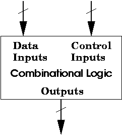
Here's a generic diagram for a combinational logic circuit.
In general, a combinational logic circuit has inputs, which are divided into data inputs and control inputs, and outputs. Control inputs tell the circuit what to do with the data inputs.
We're going to see an example of this with an ALU. An ALU consists of data inputs and control inputs. Here's a diagram of an ALU.
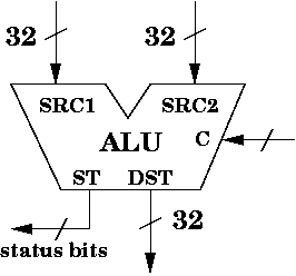
It also has a control input, labelled C. These control bits tell the ALU which operation to perform on the data inputs.
The result of the computation is sent to the output labelled DST. It is also 32 bits.
There are some additional output bits labelled ST, which are called the status bits. Basically, these bits indicate some facts about the computation. For example, they may indicate whether the output is zero, negative, or had overflow. The status bits are used for branches. For now, you can ignore them. The main output is DST.
int alu( int src1, int src2, int func )
{
  if ( func == 0 )
    return src1 + src2 ;  // return the sum
  else if ( func == 1 )
    return src1 - src2 ;  // return the subtraction
  else if ( func == 2 )
    return src1 ;         // return source 1
  else if ( func == 3 )
    return src1 & src2 ;  // return bitwise AND
}
In this case, src1 and src2 are 32 bit inputs
to the alu function. func is listed as an int,
but we might think of it as a 2 bit value. func is used
by alu() to indicate what to do with the inputs.
Finally, the value returned is the output of the alu() function. Circuits can be imagined as C/C++ functions, except circuits can do many things in parallel, where C/C++ code must do things sequentially.
We listed four functions above in the ALU code example. Here's a more extensive list of operations an ALU can support. The control bits determine which of these functions is applied to the data inputs.
Even though we may not really care where the ALU gets its inputs (since it's merely a black box that performs some computation), it might be nice to know its role in the CPU.
The MIPS ISA is very nice, because it allows us to get the input bits from very specific locations. Recall that the ALU is likely to perform some operation such as addition. Think of a typical instruction like:
add $r1, $r2, $r3
In this example, the two source registers are $r2 and $r3. We would expect the ALU to add the contents of register 2 and register 3. The contents come from the register file, which store all of the registers.
What about the control bits? What is the source of the control bits?
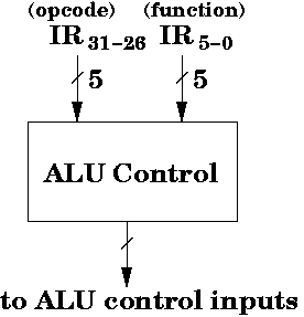
In addition to the register file, the CPU stores two special registers called the instruction register (IR, for short) and the program counter (PC, for short). The IR holds the current instruction. The instruction should contain the information we need to determine what operation to perform. In particular, the opcode (bits B31-26) and the function bits (bits B5-0) contain the information needed to determine what ALU operation to perform.
Thus, if the ALU had 3 control bits and 000 meant add, and if the IR contained an add instruction, then the ALU control circuit (which is NOT the ALU) would output a 000, which would then be fed as input to the ALU.
The output of the ALU then heads back to the register file. We'll see this in more detail in the next set of notes.
These are very common status bits for the ALU.
These status bits are used for branch instructions to indicate whether a branch should or should not occur.
We'll discuss how this works in a later set of notes.
The ALU has data inputs and control inputs. In particular, the ALU we consider has two 32-bit data inputs, and some control bits.
The purpose of the ALU is to perform computation on its data inputs, such as adding the two set of inputs, or subtracting, or performing bitwise operations.
The control bits tell the ALU which operation to perform.
The control bits are determined by a circuit, which we call the ALU control circuit, which takes the opcode and function bits from the instruction register. These bits are then converted to the appropriate control bits by the ALU control circuit. The output of this circuit is fed into C (the control inputs) of the ALU.